Back • Return Home
Solar Radiation and its Uses on Earth
John I. Yellott
Professional Mechanical Engineer and Visiting Professor in Architecture, Arizona State University
Contents:
• Fundamental Principles of Solar Energy Utilization
Heliochemical
Helioelectrical
Heliothermal
• Solar Sills and Solar Dryers
Solar Distillation
• Solar Crop Dryers
• Solar Water and Air Heaters
Solar Water Heaters
The Thermosyphon Water Heater
Solar Water Heating on a Large Scale
Solar Air Heaters
Suggestions for Building Solar Water and Air Heaters
• Solar Space Heating and Heat Storage
Heat Storage in Water Tanks
Heat Storage by Means of Rock Beds
Heat of Fusion Storage
• Solar Air Heating Systems
South Wall Air Heaters
Solar Water Heating Systems for Space Heating
• Solar Cooling
Heliothermal Cooling Systems
Natural Cooling Methods
• Solar Cooking
Solar Ovens
• Solar Furnaces
• Electricity from the Sun
Photovoltaic Devices
Heliothermal Generators
• Sundials and the Telling of Time
• Conclusions
• Appendix 1
Glossary
Time and Turning of the Earth
• Appendix 2: The Sun and its Relation to the Whole Earth
The Sun's Radiant Energy
Time and Position of the Sun
Time and the Intensity of Solar Radiation
Conclusion
• Appendix 3: Methods of Estimating Solar Heater Performance
• Appendix 4: Resources
Astronomers tell us that our sun is only one of untold billions of similar stars, in varying stages of their progression from incomprehensible origins to ultimate extinction. Our patrticular star is thought to have orginated between eight and ten billion years ago in its present rate of energy output, approximately 3.8 × 10²³ kilowatts, is caused by the conversion of mass into energy at the rate of some 4.7 million tons per second. It is expected to continue to emit radiant energy at this rate for another four billion years, so, for all practical purposes, it is the only perpetually renewable source of energy which the planet Earth possesses.
It is high time that we get on with the task of learning how to use the massive amounts of energy which the sun gives us each day, and that is what this chapter is all about. Appendix 1 is a glossary of the words and symbols used in heliotechnology, while Appendix 2 contains a more in depth mathematical and conceptual approach for the serious student of solar technology. It gives the inforamtion needed to make quantitative estimates of how big a solar device must be in order to achieve a desired result. Methods of estimating solar heater performance are in Appendix 3, and resources for further work are referred to in Appendix 4.
We will now turn our attention to the uses to which we can put this highly variable but vitally important energy resource, the sun's radiation.
Fundamental Principles of Solar Energy Utilization
There are three primary processes by which the sun's radiation can be put to technical use: (1) Heliochemical, (2) Helioelectrical and (3) Heliothermal. These are derived from the Greek word Helios, meaning "the sun." Other terms often used are: heliostatic, referring to devices which are stationary with respect to the sun or which make the sun appear to stand still; heliotropic, referring to devices which follow or track the sun, and heliochronometry, which means the telling of time by means of the sun. The latter, discussed in a later section, is probably the most ancient of the subjects to be covered in this chapter, since people have been using the shadows cast by various devices to tell time since the days of ancient Egypt.
Heliochemical
From our point of view, the first of these is by far the most important, since it is the heliochemical process called photosynthesis (Appendix 4, No. 1) which enables certain wavelengths from the solar spectrum to cause carbon dioxide and water to unite with nutrients from the soil and thus create the plants and oxygen by which we live. All of the coal, oil and natural gas that our planet has ever possessed has come from photosynthesis in ages past, and the food on which we exist today comes from that same process. We are just beginning to understand photosynthesis, but even the greatest laboratory in the world cannot equal a single blade of grass of the leaf of a tree in bringing about this remarkable process.
Man has not yet made much use of the heliochemical process, except perhaps in the field of photography, and so we will turn our attention to the remaining two processes, helioelectrical and heliothermal.
Helioelectrical
Helioelectrical devices are entirely man-made, since nature has not produced anything which convert solar radiation directly into useable electricity. These are also the most recent of the sun-powered devices to make their appearance. Really significant helioelectrical apparatus dates back only two decades to the invention of the silicon solar battery. Silicon solar cells utilize the ability of solar radiation to dislodge electrons from properly treated silicon and thus to cause an electric current to flow.
These were the first sun-powered devices to attain real and unqualified success; the exploration of space and the landing of men on the moon would not have been possible without the arrays of silicon cells which have powered virtually all of our space vehicles. It is to be hoped that the heliothermal apparatus which is about to be discussed will make an equally rapid and significant impact as that made by silicon solar cells.
Heliothermal
Heliothermal devices absorb solar radiation on blackened surfaces and convert it to heat. The black surface will attain a temperature at which equilibrium is established between the rate at which energy is being absorbed and the rate at which the absorbed energy is being lost to the surrounding atmosphere and put to useful service.
The blackened sheet of metal, heavily insulated on the side away from the sun and covered with a sheet of glass to trap the absorbed solar heat, may approach 300°F. The heat absorbed by the metal may be carried away by water circulating through tubes attached to the metal plate, or by air blowing over the sun-heated metal. The glass cover plays a vital part of transmitting as much as 90 per cent of the solar radiation to the plate and by refusing to transmit it back to the atmosphere the longwave radiation (heat) which is emitted by the plate. The glass also makes a major reduction in the amount of convective heat loss, i.e., the carrying away of heat by movement of the air at the surface of the plate.
Heliothermal devices have been used with varying degrees of success for more than a century to produce temperatures ranging from below the freezing point of water to nearly 6000°F. We will discuss them in order of the temperature at which they operate, excepting the production of ice. This will be covered in a later section, because even though ice can be produced from solar radiation, it can only be done chemically by using the process of absorption refrigeration which requires a relatively high temperature. Our discussion of heliothermal devices will begin with the solar still, which does its work at temperatures very close to the ambient air temperature.
Solar Stills and Solar Dryers
Probably the oldest intentional use of the sun's ability to produce heat came when primitive man allowed pools of salt water to evaporate to produce salt essential to the human diet. This process is still in use, as is demonstrated by the great salt works near San Francisco.
Solar Distillation
Controlled evaporation to produce fresh potable water from salt or brackish sources is a much more recent development, but, like most of the heliothermal devices which will be described in this chapter, the basic ideas can be traced back for at least a century. The first large solar still was built at Las Salinas in the Andes Mountains of Chile by J. Harding in 1872, to provide drinking water for the men and animals working in a copper mine. It was nearly an acre in extent, made of wood and glass, and it could deliver some 6000 gallons per day of pure water from a very brackish source.
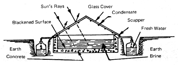
Its principle of operation is exactly the same as that of the many stills which have been built in the past few years in Australia and on the arid Greek islands in the eastern Mediterranean Ocean. Fig. 1 shows the general idea of these simple devices. A water-tight compartment, made of wood or concrete, is painted black to absorb the solar radiation which enters through the glass roof of the still. Salt or brackish water, or even sewage effluent, is allowed to flow into the channel or box to a depth of four to six inches. The incoming solar radiation heats the water, causing some of it to evaporate and this condenses on the inner surface of the glass roof.
FIG. 1 OPERATING PRINCIPLES OF A GLASS-COVERED SOLAR STILL
Since water will "wet" (Appendix 1) clean glass, the condensation takes place in the form of a very thin film which flows down by gravity into the scupper which leads the condensate off to a suitable container. The water channel is insulated by the earth. After some of the water has been distilled off, the brine which is left is flushed out at intervals. This prevents the concentration of salt from building up to the point when it will cover the bottom of the still with reflective white crystals.
The product of such a still is distilled water which can be used for drinking, for filling storage batteries or for any other purpose for which pure water is needed. Attempts have been made to use plastic films as still covers, to eliminate the weight and cost of the glass roofs, but the plastic films have not proved to be as reliable as glass. Most films are not "wet" by water and so the condensation takes place in droplets which tend to reflect the sunlight instead of transmitting it into the basin. Also, few films are completely resistant to deterioration from the ultraviolet component of the solar radiation. They are really only useful in stills which are expected to be used for a short period of time.
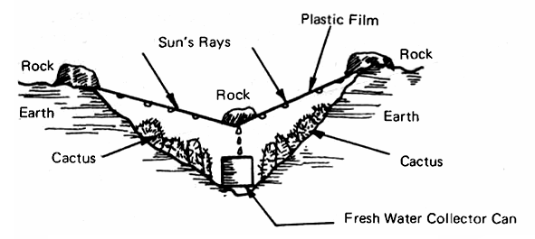
Fig. 2 shows the desert survival still devised by R. D. Jackson and C. H. Von Bavel of the Water Resources Laboratory in Phoenix. The kit includes only a sheet of transparent plastic and a tin can, since the other needed materials can be found in the desert. Even in the dryest of earth there is always some moisture and it can be distilled out by creating a heat trap, as shown in Fig. 2, by using a transparent plastic cover, a rock to weight the cover down in its center and a can to catch the droplets of moisture as they trickle down the inner surface of the plastic. This is the desert version of the ocean rescue still, developed in 1940 by Dr. Maria Telkes, using inflatable plastic bags which, in an emergency, can be used to make drinking water from ocean water.
FIG. 2 DESERT SURVIVAL SOLAR STILL
Dr. M. Kobayashi, formerly Managing Director of Nippon Electric Co. of Tokyo, proved that water can be extracted from virtually any kind of soil by the earth-still shwon in Fig. 3. He used a typical still construction, complete with cover glass and reflector to increase the amount of solar radiation reaching the earth. He has tested his still at the top of Mt. Fujiyama where the soil is volcanic ash, and in the arid deserts of Pakistan, and he has never failed to produce water that is pure and potable.
FIG. 3 EARTH STILL DEVISED IN JAPAN
The Brace Research Institute of McGill University has published plans for a simple solar still (Appendix 4, No. 2) which uses a try made by foldin gup the edges of a flat sheet of galvanized steel. The corners are soldered to make the tray water-tight and a drain pipe is soldered to the bottom of the tray. The tray is quite shallow since it is intended to hold less than an inch of water. It is painted black with a flat black waterproof plastic paint after a suitable priming coat has been applied.
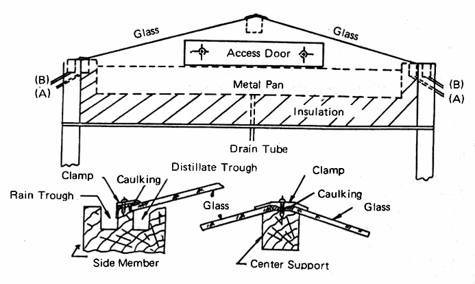
The bottom of the still is made of hardboard sheet (Masonite) 1/8 inch thick and the space between the pan and the bottom is filled with wood shavings to act as insulation. In the U.S. glass wool would probably be used as the insulating material, since it is readily available and relatively inexpensive. Fig. 4 shors a cross section of the Brace still with enough of the details to convey the essential ideas. The ends of the still are elongated triangles, made of plywood, and the sides are made of single pieces of good quality soft pine, 2 inch by 4 inch, and long enough to suit the dimensions of the tray.
FIG. 4 CONSTRUCTION DETAILS OF A GLASS-COVERED SOLAR STILL, DESIGNED BY BRACE RESEARCH INSTITUTE
The two troughs serve to carry off the distillate "A" and any rain "B" which may fall on the still (Fig. 4). The cover glasses are supported at an angle of about 15 degrees to the horizontal, with a 1 inch square supporting memeber which is appropriately beveled. The glass is given a water tight caulking at the upper and lower edges with Dow Corning No. 780 Building Sealant or its equivalent, and a galvanized sheet steel clamp is attached to the supporting memeber by flat-head screws.
The still is mounted so that the tray is level, with the long dimension running east and west, in a location which is unshaded all day long. The still is filled to a depth of about 1 inch with fresh water each morning. The glass must be thoroughly cleaned before it is installed and the outer surface must be kept clean os that the collected rainwater can also be used.
Where there is adequate sunshine and plenty of non-potable water available, a solar still such as that shown in Fig. 4 is a practical means of turning that water into drinking water at the rate of about one gallon per day for each 10 to 12 square feet of area. Larger stills will produce proportionally greater quantities of distillate, comparable to the 6000 gallons per day produced by the great stills at Las Salinas, Chile, and Coober Pedy, Australia. In summer, temperatures within the tray can be expected to reach 140°F, with considerably lower temperatures attained during the winter months.
There is a very extensive bibiliography devoted to solar distillation. Appendix 4, No. 3 will lead the reader to much of the literature devoted to this subject, including references to the work of the Commonwealth Scientific and Industrial Research Organization (CSIRO). Most of successful solar stills in use today use long concrete troughs, painted black, covered with tilted glass roofs similar to that shown in Fig. 4. Careful attention to details, particularly to the prevention of leaks, is essential to good performance.
Solar Crop Dryers
Sunshine has been used since time immemorial for the purpose of drying crops. This has traditionally been accomplished by simply exposing the crop to the sun's rays and hoping that no rain would fall until the drying process had been completed. A more sophisticated technology has been evolved during the past two decades to make more effective use of the sun's thermal power and to minimize the usual contamination associated with natural dehydration. The most common sources of contaminants are:
(a) airborne dust and wind-blown debris, such as leaves;
(b) insect infestation and presence of larvae, etc.;
(c) animal and human intereference.
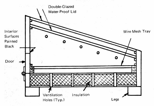
To minimize contamination and to maximize the effectiveness of the sun's rays, it is essential that the drying area be covered by a transparent material. Glass is preferred because of its resistance to determioration, while plastic films such as Mylar have merit because of their low cost and freedom from breakage due to stones, hail, etc. The Brace Research Institute has published (Appendix 4, No. 4) a very good description of a solar drying unit which can be made by anyone who has access to simple carpentry tools. This dryer is essentially a solar hot box, which can be used to dehydrate fruit, vegetables, fish, or any other product which needs to be dehydrated for preservation. It consists of a solar "hot box," with two laterys of transparent covering, which can be either double strength glass or plastic film (Fig. 5).
FIG. 5 SECTION THROUGH TRAY-TYPE SOLAR DRYER (adapted from Brace Research Institute design)
The box itself is generally made of plywood, although larger, permanent dryers may be made of adobe, brick, stone or concrete. The insulation should consist of any materials, such as wood shavings or sawdust, which are locally available and inexpensive, although these are subject to infestation by ants and termites and would have to be treated to prevent this problem. Glass wool is the preferred insulating material since it can survive any temperature which the hot box will attain, and will not support insect life.
The operation of the dryer is quite simple. The ventilation holes at the bottom and the top of the dryer allow air to enter and to carry away the moisture which is removed from the vegetables or other materials by the heat of the sun. The access door in the rear panel enables the materials to be placed on the drying tray, and to be removed when they are dry. The interior of the cabinet should be painted black, while the exteriors of the side and rear panels should be painted with aluminum paint. The numbe rof ventilation holes is determined by the amount of moisture which must be removed from the materials which are being dried.
The angle of slope of the dryer cover should vary with the latitude, but in general an angle of the local latitude minus 10 degrees will be found to be satisfactory. The use of aluminum foil within the cabinet to reflect some of the transmitted rays onto the material may be helpful. The drying trays are made of galvinized wire mesh (i.e., "chicken wire"). Where electricity is available, the use of a small fan to draw air through the dryer would be helpful, but it is not necessary.
The dryer should be glazed, preferably with two layers of glass, fitted in with adequate room for thermal expansion. Ventilation is essential so that the moisture which is "distilled" out of the agricultural material can be removed from the cabinet. This means that screened air holes in the bottom, sides, and the back of the cabinet are essential. One of the most valuable assets of such a dryer is its ability to keep produce dry during rain storms, so the glazed top should be watertight.
Experience with a cabinet dryer of this type indicates that there are upper temperature limits which should not be exceeded for most products. A hot box of this type can readily attain temperatures above 200°F if it is not ventilated, so some degree of care should be taken to prevent overheating of the materials which are to be dried.
Solar Water and Air Heaters
The heating of water and air by solar radiation is one of the oldest and most valuable applications of heliothermal technology. The variety of water heaters and air heaters is almost endless and they all operate on much the same principle.
Solar Water Heaters
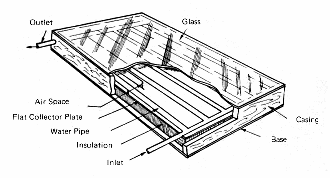
Fig. 6 shows a typical flat-plate grid collector for heating water, and Fig. 7 shows the components in an exploded cross-section. The components, progressing inward from the top, are:
(a) The glazing, which is usually double strength (1/8 inch) window glass, altough 3/16 or even 1/4 inch glass may be used if the size of the pane is so large that the wind loading requires that thickness. Tempered glass is being suggested because of its resistance to breakage, but its extra cost may not be justified in most applications. The glass must be installed with gaskets or caulking which provide enough flexibility to allow the glass to expand when it gets hot and to contract again when it cools off at night. More details on he behavior of glass and other possible glazing materials will be given later in this section.
(b) The water tubes, which, in the first generation of heaters built in the 1930's, were generally arranged in a zig-zag pattern. Today's collectors generally use a grid pattern. The metal was formerly copper, but now aluminum and steel are being more widely used for economic reasons. The tubes are usually 1/2 to 3/4 inch inside diameter, with 1 to 1-1/4 inch pipe used for the inlet and outlet headers.
(c) The flat plate, which may be any metal - copper, aluminum or steel - that has good thermal conductivity and is reasonable in cost. The term "flat plate" is used to distinguish this type of collector from the concentrator-type which will be discussed later when we deal with high-temperature collectors. The surface of the plate may be corrugated or vee-ed, or fins may be used which are perpendicular to the tubes. The major problem is finding an inexpensive way of fastening the tubes to the plate with a good thermal bond. Thermal cements (Appendix 1) are an efficient way of doing this.
FIG. 6 TYPICAL FLAT-PLATE SOLAR COLLECTOR (for heating water)
The metal plate must be coated with a radiation-absorbing paint nor plating; if painted it should be properly primed before the black coating is applied. There are special coatings available which can absorb most of the sun's rays and re-radiate very little longwave radiation, but these finishes, called "selective surfaces" (Appendix 4, No. 5) generally require very special equipment and they are really needed only when the collector is intended to operate at quite high temperatures. Flat black paint, properly applied to prevent peeling and cracking, will do a good job for ordinary domestic solar water heaters.
FIG. 7 EXPLODED CROSS-SECTION THROUGH A TYPICAL FLAT PLATE SOLAR COLLECTOR (for heating water)
(d) The insulation, which may be any low-conductivity material that is available and can withstand temperatures up to 200°F. In India, dried palm leaves have been used, but in the U.S., glass wool is the most widely used insulator because it has a low thermal conductivity (see Appendix 1 for definitions and values of this important quantity) and it is available at moderate cost in a wide range of widths and thicknesses. Remember that foil-clad insulation only makes use of the radiation-reducing qualities of the foil when the shiny surface has an air space between it and the adjacent surface. Foamed insulation is being used to some extent in collectors and it can add structural strength. Care must be taken to avoid the high temperatures which will cause the foam to melt when a double-glazed collector is exposed to the sun without any water flowing through it.
(e) The casing, which holds the collector together and, in combination with the glazing, makes it water- and dust-proof. A simple wooden box, adequately painted and fitted with a hardboard (Masonite) base, will do. Factory built collectors usually have casings made of sheet metal, rust-proofed and painted to resist deterioration.
The flow of water through flat-plate collectors can occur in many ways, as indicated by Fig. 8.
FIG. 8 SOLAR WATER AND AIR HEATERS
Fig. 8(a) shows the typical thermosyphon system, which will be described in considerable detail in the next section because it is by far the most widely-used heliothermal device. Fig. 8(b) shows a forced-circulation system, with a pump to take water from the lower part of the storage tank and force it upward through the heater to the top of the tank. An extension to the vertical down-comer is shown to represent an air-vent, which will cause the collector to be drained of its water whenever the pump stops. This is necessary to prevent freezing in regions where the outdoor air temperature falls below 32°F for any protracted period of time. An alternative is to use a mixture of water and antifreeze (ethylene glycol is most widely used and readily available), but this requires the use of a heat-exchanger (Appendix 1) between the water circuit and the storage tank. In addition, any antifreeze liquid is certain to be relatively expensive and it may be highly poisonous.
This system would use a thermostat designated "t" to sense the temperatures of the water in the tank and the surface of the collector. When the sun is shining brightly enough to heat the collector surface to a temperature above that of the water in the tank, the pump is started, and it runs until the sun has moved to a position in the sky where its rays will no longer produce enough heat to enable the collector to operate.
Fig. 8(c) shows the "Skytherm" system invented by Harlod Hay of Los Angeles, in which a steel ceiling-roof is covered with water which is contained in shallow plastic bags (e.g., water beds). The insulating panels shown above the water bags can be moved away horizontally by pulling on a cable (not shown) so that the sun's rays can warm the water during sunny winter days. The water will in turn warm the metal ceiling-roof which then becomes a radiant heater for the room below. At night the panels are moved back to cover the water bags and eliminate loss of heat to the cold night air.
During the summer the operation is reversed; the panels remain over the bags during the day and they are rolled back at night so that the water can lose heat to the night sky. During the hottest part of the summer, water can be sprayed on the bags. Some of this exposed water will evaporate, cooling the enclosed water and thus causing the ceiling to function as a radiant cooler.
The "Skytherm" system was tested extensively for eighteen months in Phoenix during 1967-68. It kept a small, one-room structure above 68°F in winter and below 80°F in summer for all except 1% 13,140 hours of test conditions. A full-scale "Skytherm" residence is currently in operation at Atascadero, California.
Fig. 8(d) shows a gravity system in which the pump raises the water to a distribution pipe along the tope of the collector and gravity makes the water flow downward over the black flat plate in the collector and back to the tank. This is the system which Dr. Harry Thomason uses in his "Solaris" homes. The advantage to this system is that there are no pipes to form a grid in the collector, thus reducing the cost and weight of the unit. A thermostat performs the same function here that it did for type (b) and the vent at the top of the piping causes the water to drain back to the tank whenever the pump stops.
The Thermosyphon Water Heater
The simplest and most reliable heliothermal device is the thermosyphon solar water heater which is shown in Fig. 8(a), and in more detail in Fig. 9. This combines a flat plate collector with an insulated water storage tank mounted high enough above the collector so that the cold water in the downcomer pipe will displace by convection the sun-heated water in the collector tubes. This causes a slow but continuous circulation of water downward from the bottom of the tank, upward from the collector, and back to the upper part of the tank. The action will continue as long as the sun shines on the collector. In a good sunny location, free from shadows throughout the entire day, a 4 foot × 8 foot collector will give 40 to 50 gallons of hot water per day. The temperature of the water in the upper part of the tank will vary from 165°F on a hot summer day to 115°F on a cold winter day.
FIG. 9 TYPICAL THERMOSYPHON SOLAR WATER HEATER
A single layer of glass is gnerally adequate to reduce the heat loss from the surface of most collectors, but in very cold areas double-glazing is desirable. Care must be taken in applying glass, to make sure that it is free to expand or contract, because the inner glass will get very hot by radiation and convection from the collector plate, while the outer glass will remain relatively cool due to the loss of heat to the outdoor air.
The bottom of the storage tank should be at least 1 foot above the top of the collector and the connecting pipe from the downcomer to the bottom header should slope downwards towards the collector.
All piping should be insulated and the tank should be completely surrounded with as much insulation as possible, up to 6 inches in thickness. This should be covered with a thin sheet-metal jacket painted in some dark color to take advantage of the sun's ability to help keep the tank warm during the day.
There are many other ways (Fig. 10) to produce water heater collector plates. The Australians have traditionally used copper tubing soldered to a copper sheet as was used in thousands of solar water heaters built a generation ago in the U.S. Now copper is too expensive for large scale use, although its resistance to corrosion and its ease of forming and soldering give it a major advantage over steel and aluminum.
FIG. 10 FLAT PLAT COLLECTOR TYPES
A factory-made collector plate is shown in Fig. 10(a), representing an integral tube-in-sheet which is made in the U.S. under the Roll-Bond® patents held by the Olin Brass Co. Their process involves the printing (using a very special "ink") of the desired tube pattern on one flat sheet of aluminum. A sandwich is then made by putting a second sheet of aluminum over the first and bonding the two together with heat and pressure over their entire surfaces, except for the printed areas. The tubes are then created by inserting a special needle into an unbonded portion of the edge and inflating the tube pattern with a pressurized fluid. This is the process by which virtually all refigerator freezing compartments are made, and patterns of extreme complexity can be produced on panels of relatively large size (up to 3 or 4 feet by 12 feet).
The one major problem encountered with aluminum tube-in-sheet is the corrosion which generally occurs when untreated water comes into contact with bare aluminum. The Showa Aluminum Co. of Jpan has a U.S. patent on the use of zinc powder in the special "ink" used in the Roll-Bond® process and this produces the equivalent of a galvanizing action on the water passages which, according to Showa, makes them entirely resistant to corrosion. When these panels become available in the U.S., they will be very valuable components of the large number of collectors which are going to be needed here.
The actual temperature of the water used for domestic purposes in the U.S. ranges from 100°-110°F for bathroom purposes, which is about as high as the human skin can tolerate. Dish washing, to remove grease, may require higher temperatures, although proper detergents can take care of that problem in the 100°F range quite nicely. Institutions are required by law to maintain 180°F in their dishwashers for sterilization, and this is above the limit attainable by a single-glazed collector during most of the year. For such purposes, the solar water heater would be used as a preheater, thus conserving a substantial part of the energy that would otherwise be required.
The Japaense have developed a wide vareity of solar water heaters; new types are also being announced in Australia and the U.S. with each new issue of Popular Science. Some fo these will undoubtedly prove to be successful, but others will lack either the long life or the high performance which a successful installation must have. Beware of the low-cost plastic variety, which are likely to have a very short life and to be susceptible to the high temperatures which are reached very quickly when un-cooled black surfaces are exposed to the sun.
Solar Water Heating on a Large Scale
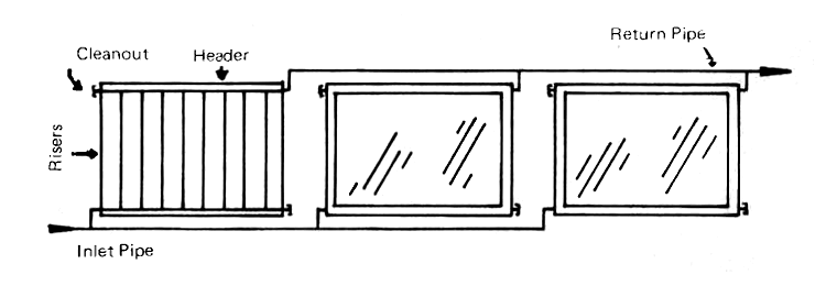
The heating of large quantities of water can be done by using a number of individual collectors connected in parallel. The Australians (Appendix 4, No. 7) who have had much experience with such installations, believe that not more than twenty-four riser tubes should be used in parallel coming from a single header. They have demonstrated that very large batteries of collectors can be made to work satisfactorialy by using the arrangement shown in Fig. 11.
FIG. 11 METHOD OF CONNECTING LARGE COLLECTOR BANKS IN PARALLEL
They have also shown that relatively high temperatures can be attained for large quantities of water for industrial and commercial purposes by using three types of collector batteries in series. The first, receiving the coldest incoming water, are not covered with glass and hence are relatively inexpensive; the second battery is comprised of single-glzed collectors which are more expensive and also more efficient with warmer water. The third batter, which elevates the water to its final temperature, is double-glazed; these are the most expensive units, but they are also the most efficient at high operating temperatures.
Solar Air Heaters
Fig. 8(e) shows a simple and inexpensive air heater, consisting of a cover glass (plastic film may be used, too), a corrugated plate of sheet steel or aluminum painted black, a space through which the air can flow, a layer of insulation and a Masonite or plywood backing to keep the assembly water-proof. The air can be made to flow by means of a fan or blower, or, if the system is properly designed, it will rise due to convection (the "chimney effect") because the heated air is lighter than the cold air outside.
Air heaters are much less expensive than water heaters because there is no need to worry about freezing, and any leakage which occurs will not cause the kind of damage which water can create. The drawback to air systems is the fact that they are larger, more expensive and more power-consuming than the small pumps used with some solar water heating systems [Fig. 8(b) and (d)]. Also, the ducts which are used to carry the air are much larger and more costly than the pipes used with water systems. Each type has its advantages and disadvantages, and each prospective installation must be given careful thought to make sure that the best possible choice is made.
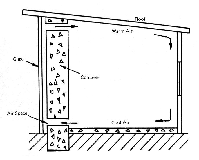
The simplest of all solar air heaters, and one which is in increasingly wide use now, employs a heavy southfacing vertical concrete wall (Fig. 12) which is painted a dark color and covered with a sheet of glass. An air space runs between the concrete and the glass, and the chimney effect causes the heated air to rise. Openings at the bottom and top of the wall allow the cold air along the floor to enter the air space and similar openings at the top provide an opportunity for the warm air to re-enter the room behind the wall. The air then circulates through the room, warming the walls and the occupants. Small electric baseboard heaters are used to provide heat during long periods of bad weather.
FIG. 12 TROMBE-TYPE SOLAR SOUTH WALL AIR HEATER USED AT ODEILLO, FRANCE
The overlapping glass plate air heater shown in Fig. 10(f) was invented during World War II by Dr. George Löf, who uses this system in his own home in Denver. The plates are actually divided into two segments, with the upper piece being clear and the lower piece being black. The division was found to be necessary when the first prototype was tested using single sheets of glass with the lower half painted black. These promptly broke from thermal shock as soon as they were exposed to the sun, because the lower part immediately became hot, while the upper part remained cool. Dividing the glass sheets into two parts cured this problem completely, and the Löf house in Denver has been operating satisfactorily since the late 1950's.
Flat metal plates, painted black and covered with glass or plastic glazing, will do a good job of heating air, as Dr. Telkes proved in the solar house which she built at Dover, Massachusetts, in 1939. However, the heat transfer from the metal to the air is improved if the plates are corrugated to increase the amount of surface available for heat transfer. The Australians are making good use of thin copper air heaters, with the copper corrugated into small vees and treated on its outer surface to become selective in its ability to absorb solar radiation and yet not re-radiate much longwave radiation.
Suggestions for Building Solar Water and Air Heaters
There are no hard and fast rules for building satisfactory solar heaters, nor are there any precise dimensions which must be followed. Generally speaking, there should be a single glazing at least, spaced about 1 inch above the collector plate. Glass will generally give much longer life than plastic glazing, but if a shortened life is acceptable, either Mylar or Tedlar (both are duPont films) will do almost as good a job as glass except at very high temperatures.
There are no precise dimensions which must be specified for either air or water heaters. Metal sheets, plywood, Masonite and similar materials are generally available in 4 foot by 8 foot dimensions. Aluminum, galvanized steel, and copper are usually available in 2 to 3 foot widths and almost any specified length. Glass wool insulation is available in thicknesses ranging from 1 to 4 inches. Glass can be purchased in a wide range of dimensions, but individual sheets larger than 4 feet square are difficult for one person to handle.
A 4 foot by 4 foot module, as used in Australia, is a very good choice for a water heater, since it will weigh close to 100 lbs. and that is as much as two people can handle readily, particularly when they are working on a rooftop with a steep slope. For air heaters, the weight is much less and 4 foot by 8 foot units can be conveniently carried and installed by two people. Corrugated aluminum is much lighter than corrugated sheet steel of the same dimensions and it generally costs little if any more per square foot since the thickness of the aluminum can be less than the steel.
Dr. Thomason gives quite detailed instructions for building the aluminum water heater which is the main feature of his "Solaris" house (Appendix 4, No. 8). The construction details of most of the other solar houses which have been built during the past three decades are to be found in the articles published by their builders and many of them are well described in Introduction to the Utilization of Solar Energy by Zarem and Erway (Appendix 4, No. 3).
Factory-produced water heaters are now available from a number of manufacturers, and more will soon be on the market. The only type which cannot be built by the builder of average skills is the Roll-Bond® variety which is made of aluminum and requires special welding equipment.
A quite satisfactory water heater can be made using 1 inch galvanized steel pipe as the headers and 1/2 inch galvanized tube as the risers. Thin galvanized sheet steel can be used as the collector plate; this is easier to handle if it is used in the form of strips about 6 inches wide. Drill holes large enough to accept the 1/2 inch tubes at 4 inch centers in the headers and solder the tubes into the headers after the headers have been threaded on both ends.
This will produce a grid of pipe and tube which will weigh less than 30 pounds; the addition of the galvanized steel strips will add another 10 to 12 pounds of weight. Let the steel strips overlap lengthwise and solder or cement the tubes to the strips.
Mount the collector in a box with wooden sides and a Masonite bottom. A soft Neoprene gasket and an aluminum cover strips will give the glass the necessary room to expand and contract, while you retain the water-tight feature which is essential. Three inches of glass-wool insulation should be adequate and a few small holes may be drilled along the bottom of the collector box to allow it to "breathe" as its temperature changes. A flat black paint should be applied to the collector plate and the tubes, after they have been primed with the material which is recommended by the paint manufacturer.
The water inlet connection may be made to either end of the bottom header and the other end should be closed with an ordinary 1 inch standard pipe cap. This cap can be removed at appropriate time intervals to remove dirt and scale from the header. The outlet connection should be made at the opposite corner of the upper header, so there will be approximately equal resistance to water flow across the collector grid.
The use of a water softener ahead of the solar collector will greatly extend the useful life of the collector by preventing the formation of scale on the inner surface of the piping in the hot portion of the collector.
Air heaters are much easier to make, since they require only an air-tight box with a glazing material on the top; this may be either glass or a Tedlar or Mylar film. The heat-absorbing panel may be corrugated or rolled sheet metal, preferably aluminum, with a "dead air space" about 1 inch wide between the glazing and the collector. The air-flow space will be along the back of the aluminum, and both sides of the metal should be painted black. The top or upper surface must be black to absorb the solar radiation which will be transmitted through the glazing. The lower surface should also be black so that it can radiate heat to the covering over the glass wool insulation and allow that surface to help in the air heating process.
Unless you are an expert at cutting glass, have this job done for you at the hardware store where you buy the glass. A badly-cut piece of glass is likely to have defects along the edges and when temperature differences begin to occur across the glass, as they will when the plate begins to be heated by the sun, thermal stresses may be set up which can break the glass. Four foot by four foot lights (panes) of glass are also much easier to replace if breakage does occur due to hail stones or other objects which may strike the glazing. Breakage of the glass covers due to hail or stones can be lessened by the use of 1/2 inch wire mesh, supported on an angle-iron framework several inches above the glass. The use of this screen reduces effective absorber area by about 15%, so the total absorber area should be increased to compensate for this reduction.
Solar Space Heating and Heat Storage
Solar space heating may be accomplished in many ways and again there are no hard and fast rules. Before undertaking to heat a building by solar energy, a competent estimate must be made of the amount of heat which the structure will need under adverse winter conditions and at night. The solar heater must be able to provide not only the heat which will be needed hour by hour during a sunny day but it must have additional capacity so that heat can be stored during the day for use at night or during cloudy days.
There are three methods of heat storage which are in use today: the first two representing relatively low technology but complete feasibility. The thrid, although it has been under study for many years, is still in the developmental stage.
Heat Storage in Water Tanks
Large tanks, filled or almost filled with water, represent the best method that is presently available to store large amounts of heat or cold.
Every substance possesses its own "specific heat," which is the amount of heat in Btu's needed to raise the temperature of that substance 1 degree F. On a pound-for-pound basis, one can store more heat in a substance of higher specific heat than in a substance of lower specific heat. Water has a specific heat of 1.0 Btu/lb./°F, an antifreeze such as ethylene glycol has a specific heat of 0.6, but almost all solid materials from rocks to iron and aluminum have a specific heat of 0.2 Btu/lb./°F.
Water weighs 62.4 pounds per cubic foot or 8.34 pounds per gallon. If we heat water 10 degrees F above the temperature at which we need the heat, we can store 624 Btu in a cubic foot or 83.4 Btu in a gallon of water. Assume that it is house heating which we wish to accomplish and that by using a very efficient system of heat distribution we can use water as cool as 90°F to heat the house.
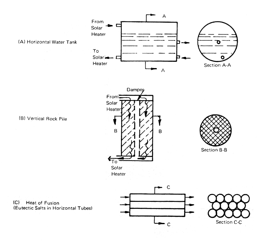
If we store hot water at 150°F in a cylindrical steel tank, as in Fig. 13(a), we can store 62.4 lb./cu.ft. × (150°F - 90°F) = 3774 Btu in a cubic foot of water or 8.34 lb./gal. × (150°F - 90°F) = 500.4 Btu in a gallon. A 2000 gallon tank of water will thus be able to store about 1,000,000 Btu's at a temperature difference of 60°F.
FIG. 13 HEAT STORAGE METHODS
If we insulate the tank with 6 inches of glass wool or, even better, 6 inches of urethane foam, we will lose only about 1000 Btu per hour through the glass wool and half that amount through the urethane (assuming that the tank is 6 feet in diameter and 10 feet long).
The storage of cold is not quite so simple, since we cannot use such a large temperature range without running into the complication of freezing the water. We may well want to do just that, as we will see in the heat-of-fusion section upcoming, but assuming that we want the water to remain in the liquid state and that we want to use it for cooling at 55°F, we have only 23 degrees of temperature at our disposal (water freezes at 32°F). The 2000 gallon tank contains 8.34 lb./gal. × 2000 gal. = 16,680 lbs. of water and can thus store about 16,680 lbs. × 23°F = 383,640 Btu's of "coolth," as compared with nearly three times that much when we are storing "warmth."
Now we see that, if we can allow a 60°F temperature rise and fall, we can store about 1,000,000 Btu in a 2,000 gallon tank but if we restrict ourselves to the 23°F temperature rise and fall for cooling, we will need a tank nearly three times as large, or almost a 6,000 gallon tank. For a 6 feet diameter tank, the length will stretch out to about 30 feet. Obviously, if we want to store very large amounts of "coolth" in a tank of water, the tank is going to have to be very large.
The tank should have an outlet connection at one end, near the bottom, from which the water can be pumped to the solar collector, and a return inlet, above the water level, thus leaving some air space in the tank. An access hold, large enough for someone to get inside the tank, will be a wise precautionn (not shown in Fig. 13(a)). There should be two connections on the far end, one above the center of the tank to supply the water to the distribution system and one near the bottom to receive the return water.
The mechanics of storing heat in water are simple; in addition, water is available almost everywhere. The disadvantages are the space, weight (8.3 tons for 2,000 gallons, 25 tons for 6,000 gallons), and the cost of a steel tank with a 1/4 to 3/8 inch thick shell. Despite these disadvantages, water storage remains as the only practical system when we are using water as the medium for collecting and distributin gheat.
Heat Storage by Means of Rock Beds
The ability of a solid to transfer heat is a function of its surface area per unit volume; the more surface area, the greater the ability to transfer heat per unit volume. The ability of a material to store heat is a function of its density per unit volume and its specific heat. A solid cubic foot of basalt has a density of about 184 pounds, but a surface area of only six square feet, making it a poor candidate for a heat transfer system, even though it is a good means of heat storage. If this big cube is broken into many 1/2 inch cubes, we will have 13,824 small cubes and their total surface area will be 144 square feet, giving us a much better heat transfer situation. However, in trying to pack the cubes helter-skelter into the original one cubic foot container, we will find, because of air spaces, the cubic foot will only hold about 89 pounds. This will still give us about 70 square feet of heat transfer surface, compared to the 6 square feet of the original block.
Going back to 23°F as the temperature range over which we were operating with the water tank, 1 cubic foot of basalt pebbles can store 89 lbs. × 0.2 Btu/lb./°F × 23°F = 409 Btu. If we are concentrating on heating and can allow a 60°F temperature difference, we can store almost three times as much heat; 1,068 Btu per cubic foot or 24,000 Btu per ton. To store 1,000,000 Btu with the 60°F temperature range, we would need 41-2/3 tons, which is a formidable pile of rocks.
The practical way to handle a rock pile storage situation is to use the arrangement show in Fig. 13(b), with the rocks contained in a cylinder, and their weight supported by a steel grill at the bottom of the container. A central pipe with a damper will allow the rocks to be by-passed when the heat is needed directly in the structure.
The air-heated house erected by Dr. George Löf in Denver in 1959 uses two large cylinders, 3 feet in diameter and 18 feet high in the center of the building, to store 12 tons of 1 to 1-1/2 inch rock with a bulk density of 96 pounds per cubic foot. The Thomason houses in Washington, D.C., use 25 to 50 tons of "fist-sized" rocks to provide supplemental heat storage as well as heat transfer surface. Two demonstration houses erected by the writer for the U.S. government in 1958, one in Casablanca and one in Tunis, used the system shown in Fig. 13(b), with a vertical rock pile contained in a Sonotube cylinder.
Rock piles have the advantage that they can neither freeze nor leak, but their capacity is limited. However, they can be safely used under a building since, once they are put in place, very little harm can come to them. The Australians have made particularly effective use of rock beds in the device called the "Rock Bed Regenerator," which will be discussed later.
Heat of Fusion Storage
When a tank of water is cooled by refrigeration, it will give up 1 Btu per pound for each degree that it is cooled until it gets to 32°F. At that temperature, ice will begin to form and there will be no further change in temperature until another 144 Btu (called the "heat of fusion") have been removed. One hundred forty-four Btu per pound must be added to the ice-water mixture to melt the ice and return it to liquid form again. Its limitation is that 32°F is the only temperature at which water will freeze into ice and then melt back again to water.
There are other substances which freeze and melt at more convenient temperatures; the most widely known being Glauber's salt, sodium sulfate decahydrate (Na2SO4 · 10H2O). This melts and freezes again at 88° to 90°F, with a heat of fusion of 108 Btu per pound. There are many problems connected with this and similar materials. Their potential value in the storage of warmth and coolth lies in the fact that 1,000,000 Btu's can be stored in only 5 tons of salt as compared with 25 tons of water and 125 tons of rocks (with a 20°F temperature swing).
Dr. Telkes of the Institute of Energy Conversion at the University of Delaware has devised ways of adding small amounts of other substances to heat of fusion materials to make them behave properly. The major difficulty appears to be that the heat of fusion materials, unlike water, sink when they freeze and it is not a simple matter to find ways to make them become homogenous liquids again when they melt. The first attempts to use Glauber's salt in relatively large drums were unsuccessful and now Dr. Telkes has turned to long slim plastic tubes (Fig. 13(c)), similar in shape and size to fluorescent lamps, to provide both storage for the materials and heat transfer surface for the University of Delaware Solar House, "Solar One." Her latest combinations will provide storage of warmth at 120° to 126°F and coolth at 55°F.
Solar Air Heating Systems
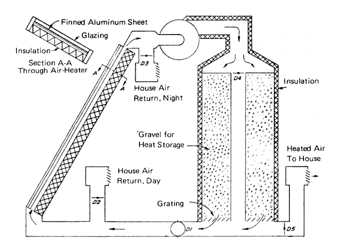
Fig. 14 shows a simple solar air heating system which can be used to provide heat and store excess energy during the day by heating the gravel in the storage tank. One fan and five dampers are needed to enable air to be drawn through the air heater and then to be sent either through the storage cylinder and back to the collector, or diverted directly to the house on cold days. At night, the collector may be by-passed and all of the house air may be circulated through the storage cylinder. For use in most parts of the U.S., an auxiliary electric heater, probably in the form of a grid of resistance wire, would have to be used to guarantee comfort during prolonged periods of bad weather. A fireplace with a Heatalator [see Biofuels - Wood] would do equally well in rural areas where firewood is available.
FIG. 14 SOLAR AIR HEATER SYSTEM WITH VERTICAL ROCK BED HEAT STORAGE
For heating small, single-story houses, air heaters have a number of advantages, including simplicity and low initial cost. However, the duct-work for the movement of air requires careful planning. Air ducts are many times larger than water pipes in cross-section, and problems can easily develop when one tries to run the ducts in walls and around structural members. Duct-work generally must be purchased from sheet-metal shops, where some pieces probably will have to be custom-made. Fortunately, the temperatures involved in most solar air heaters are such that the air may safely be conveyed in insulated passages between floor and roof joists and through the air spaces which exist in stud walls. Care must be taken to ensure equalized flow through all parts of the air heater. This will generally involve some balancing of the air flow by means of dampers after the system is built.
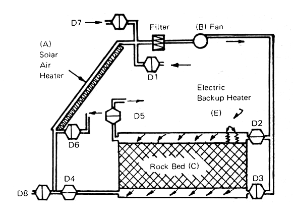
FIG. 15 SOLAR AIR HEATER WITH ROCK BED HEAT STORAGE (8 dampers)
In summary, an air heating system needs the four elements shown in Fig. 15: (a) is the collector, facing south, steeply tilted and insulated so that the collected heat will go into the air and not be wasted. A fan (b) is needed to circulate the air. A filter on the fan will minimize the dust and pollen problem within the house. The rock bed (c) provides storage of heat in winter and storage of coolth in other seasons when the air at night is cold enough to cool the rocks so that they in turn cool the house during the day. An auxiliary heating system in the form of the electric grid (e) can be used to heat the house directly on cloudy, cold winter days or to store heat in the rock bed by properly setting the dampers. Fig. 15 has a maximum of flexibility because its eight dampers permit outdoor air to be brought in, blown through the rockbed and then out again. The rockbed can thus be cooled down at night and the house air can be cooled during the day by blowing it through the cooled rocks.
South Wall Air Heaters
A number of houses have been built in southern France using the concept shown in Fig. 12. This is an outgrowth of work done during the past decade by Dr. Felix Trombe of the Solar Energy Laboratory at Odeillo. The major actvity at Odeillo is centered around the great solar furnace, but the building which houses the nine-story solar concentrator, and many of the staff homes in the vicinity, use south wall heaters during the winter months, with electric auxiliary heaters for long periods of low insolation.
This idea is just beginning to be used again in the U.S., although the Telkes-Raymond house in Dover, Mass. used vertical south-wall heaters, and "Solar One" at the University of Delaware is employing this system, too.
Solar Water Heating Systems for Space Heating
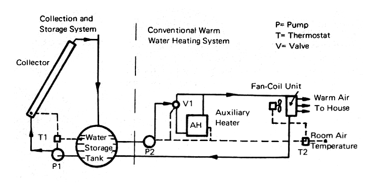
The basic principles of a solar space heating system using water instead of air as the heat transfer fluid are given in Fig. 16. A collector similar to Fig. 6, or Fig. 10 (a)-(d), is mounted on a south-facing exposure or a flat roof of a structure. Heat storage is provided by an insulated tank which can hold from 2,000 to 20,000 gallons of water depending upon the size of the building and the length of time that heat must be provided from storage.
FIG. 16 SOLAR SPACE HEATING SYSTEM USING WATER
The house heating system works independently of the solar collecting and storage system (Fig. 16), since the solar-system pump, P1, goes to work whenever the solar thermostat, T1, senses that the temperature of the collector panel is warmer than the water in the storage tank. The pump runs at constant speed and so the temperature of the water leaving the top of the collector will vary from a few to many degrees above the tank temperature.
When the thermostat senses that the collector panel is falling below the tank temperature, the pump will stop and all of the water in the collector panels will drain back into the tank. The system is thus "fail-safe," because it will be protected against freezing since the system will drain itself whenever the pump stops because of power failure or from a signal from the thermostat. There will be enough inertia in the system to prevent it from stopping if a passing cloud happens to cross the sun, bit it will stop and remain shut down if prolonged cloudiness sets in.
The actual heating of the building is done by any conventional warm water system (e.g.: water circulation pipes and radiators) into which the circulating pump P2 will supply warm water from the storage tank. When the house thermostat T2 calls for heat, it starts P2, and valve V1 directs the warm water into the house heating system, indicated in Fig. 16 as a fan-coil unit. This consists of a fan or blower, driven by an electric motor, and a heater containing finned tubes through which the water flows. In many homes, the fan in such a system runs continuously to give air circulation even when heat is not required. A filter will add to the comfort of the occupants of the house by removing dust and pollen at very little added cost.
Generally, the solar heat collection and nstorage system will be designed so that enough heat will be available in the storage tank to carry the house through several cold, sunless days. However, it is not feasible to store enough heat for every possible contingency and so an auxiliary heater must be provided. Shown in Fig. 16, this may be a fuel-fired heater or an electric resistance heater. If an auxiliary heater msut be used for many hours per year, or if the region is one where summer cooling is needed as urgently as winter heating, then a heat pump (Appendix 1) is the economical answer to this problem.
The heat pump can use cool or even cold water from the storage tank as its heat input and use a small amount of electric power to raise the temperature of the water up to the point where it can do the heating job. This system is discussed in detail in the articles cited in Appendix 4, No. 9.
The system shown in Fig. 16 has been used in many buildings, including the MIT solar houses which were built in the 1930's. These used large south-facing collectors which constituted the south-facing portion of the roofs, and large water tanks in the basement. Several experimenters have used bare metal roofs with tubes integral with the metal roofing (similar to Fig. 10(a)) as their heat collectors, with water storage tanks and heat pumps to raise the temperature of the circulating water to the point where it can warm the building. Prominent among these experimenters were Mr. Yanagimachi of Tokyo and Mr. and Mrs. Raymond Bliss of Tucson, who designed the University of Arizona Solar Laboratory which was in use for several years until it was torn down to make way for the University's Medical School.
There are two other water heating systems which should be mentioned in this section, the first being the "Solaris" houses built by Dr. Thomason in a suburb of Washington, D.C., in 1959, 1960 and 1963. The Thomason houses all use the open-flow system shown in Fig. 10(d). The collectors are mounted on steeply-pitched south-facing roofs and they receive their water from a perforated pipe which runs along the ridge of the roof. A large (1,600 gallon) water tank in the basement provides the major heat storage and this is surrounded by 50 to 60 tons of river rock. These rocks provide additional heat storage and the heat transfer surface which is needed to warm the air which is circulated through the house by a small blower.
The collectors are covered by a single layer of glass and they drain automatically whenever the pump is shut off by the thermostat which senses the temperature of the collector surface. Corrugated aluminum roofing, primed and painted black, is used as the collector surface. This is probably the lowest cost collector panel in use today. Appendix 4, No. 8, gives additional details on the "Solaris" system.
The "Skytherm" solar heated and naturally cooled system (Figs. 8(c) and 10(g)), invented by Mr. Hay, now has its first full-scale application. A building of this design is now in regular use at Atascadero, California. Professors Kenneth Haggard and Philip Niles of California State Polytechnical University did the architectural design and engineering. Technical assistance came from Professor Philip Niles on the instrumentation phase. Funds for building the house were put up by the inventor, Mr. Hay. HUD (the Department of Housing and Urban Development) contracted with Cal Poly to instrument and monitor the operation of the house.
The "Skytherm" system is particularly well adapted to teh southwest desert, where the skies are generally clear both winter and summer, and where the summer humidity is low. Daytime temperatures may be very high (110°F and above) but the "Skytherm" system has demonstrated its ability to cope with them.
Another solar-water heated house which should be mentioned is the residence of Mr. and Mrs. Steve Baer, near Albuquerque, New Mexico which uses steel barrels filled with water, behind single glazing, to absorb the winter sun on the southern exposure of the house. An insulating panel, hinged at the bottom, is lowered when the sun begins to strike the south wall, admitting the sun's rays to warm the blackened ends of the barrels. The barrels serve as radiators to warm the building, and an ingenious device allows shutters to open automatically whenever the house needs to be cooled. The exterior insulating panel is raised at night to retain the heat which the barrels have collected during the daylight hours.
Solar Cooling
Solar cooling is something of a misnomer, since there is actually no way by which we can use the heat of the sun directly to produce cooling. However, we can use the heat to produce hot water or steam, and with that we can refrigerate, using the process known as absorption refrigeration. There are natural cooling methods which are treated in the next section which might be considered to be sun-related but they do not actually use solar radiation as such.
Heliothermal Cooling Systems
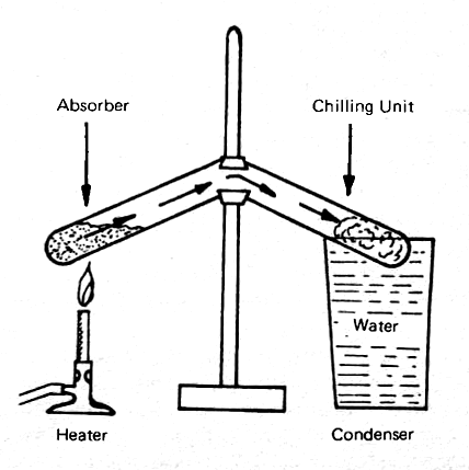
The process by which the sun's radiant heat is used indirectly to produce cooling is known as "absorption refigeration." This process was discovered almost accidentally by the British scientist, Michael Faraday, in 1824. Faraday was trying to make liquid ammonia, using the apparatus shown in Fig. 17. It consisted of a U-shaped test tube, with silver chloride saturated with ammonia in the left leg, and nothing, at first, in the right leg. A glass of water, or some similar simiple cooling means, was provided for the right leg, and a source of heat, shown as a Bunsen burner on the left. As Faraday applied heat gently to the saturated silver chloride, the ammonia gas was driven off, and it condensed as a liqui on the right side.
FIG. 17 FARADAY'S 1824 DEMONSTRATION OF ABSORPTION REFRIGERATION
Faraday then proceeded to cut off the heat, and go on about his business. When he returned, he found, much to his surprise, that the liquid ammonia had disappeared from the right side of the apparatus, but the outer surface of that side was covered with ice. He reasoned, quite correctly, that the ammonia went back into absorption in the silver chloride. This was the first absorption refrigeration process, and, about one hundred years later, this principle was used for household refigerators.
The ammonia-water absorption system was discovered somewhat later. Here the ammonia is the refrigerant and the water, instead of silver chloride, is the absorber. Water can absorb very large quantities of ammonia when it is at low temperature, but, when the water is heated under high pressure, it will give off the ammonia as a gas. This ammonia can then be condensed back to liquid form and allowed to expand through a valve, where some of the ammonia will evaporate and cool down the rest of it.
This form of absorption refrigeration has been very widely used, with low pressure steam as the heat source. The only mechanical work involved is the power needed to run a small pump to raise the pressure of the ammonia-water. In a high pressure "generator," heat is then applied to drive the ammonia away from the water. Cooling must also be applied at this point to cool the water down again, and to condense the ammonia. So, both heat, and cooling water, such as that obtained from a cooling tower or an evaporative cooler, must be provided.
The ammonia-water system is also under pressure, and building codes require that such apparatus be used in outdoor locations. The chilled fluid which results from this process, generally cold water, can be taken indoors and used to cool air. This system is widely used wehre there is a large quantity of low pressure steam available which would otherwise be wated or where very hot water is available.
The absorption process which is being studied in a number of experimental buildings uses lithium bromide as the absorbant and water as the refrigerant. Water has been used as a refrigerant for many years, using centrifugal compressors or steam jets to reduce the pressure on a tank full of water. This causes enough of it to evaporate to chill down the remainder. The compressed water vapor is then condensed by the use of water from a cooling tower or a similar source. It then goes back to the tank to complete the cycle and to be re-used. Attempts have been made to use steam generated in solar boilers to power such as system, but they have not been successful.
The lithium bromide system uses the ability of that substance to absorb large quantities of water when it is relatively cool, and to give up the water vapor when it is heated. The temperature to which the heating must proceed is about 200° to 210°F in conventional commercial units, such as those manufactured by the Arkla-Servel Company. Newer versions of the lithium bromide-water systems use solar-generated hot water at 180° to 200°F to regenerate the strong lithium bromide-water solution, and thus to drive off the water, which must be cooled before it can go back into the chiller tank to complete the cycle and continue the process.
The major difficulty with solar-powered absorption refrigeration at the present time is the temperature at which it has to operate and the relatively low Coefficient of Performance. The latter is simply the ratio of the cooling effect to the amount of heat that must be generated to produce this effect, frequently measured in "tons of refrigeration" (Appendix 1). The Coefficient of Performance of a typical lithium bromide absorption system is no higher than 0.6, as opposed to the 3.0 or better attained by even a small compression refrigeration system driven by an electric motor.
Temperatures in the 200°F range are not easy to obtain with solar collectors, even if two cover plates and a selective surface are used. The efficiency of collection is likely to be no higher than 50% at noon and an hour or two before. After that time, the efficiency falls off rapidly, as the sun moves away from its noon position, and the day-long efficiency of a collector operating at 200°F is likely to be no more than 30%.
There are many other combinations, aside from ammonia-water and lithium bromide-water, which can be used in absorption systems, and these are being carefully reviewed now to see whether a system can be developed which will operate at lower temperatures, with a higher Coefficient of Performance than those which characterize today's absorption systems. Dr. Erich Farer and the Solar Energy Laboratory, University of Florida (Appendix 4, No. 10) are doing significant work in solar cooling.
Natural Cooling Methods
There are two natural cooling methods which have been used with considerable success in appropriate climatic conditions. These are (1) night sky radiation and (2) evaporation.
Almost everyone has observed the effect of night sky radiation when they have noticed frost on the ground early in the morning, even when the air temperature has not dropped to 32°F. The reason for the cooling of the ground to the freezing point is that, depending largely upon the amount of water vapor in the atmosphere, the sky is a good absorber of radiation. When the sky is very dry, the apparent temperature of the sky, as far as the ground heat losses are concerned, may be very low.
The term "noctural radiation" is again a misnomer, because radiation from surfaces on the earth to the sky proceeds all day long, but it is generally masked by the incoming solar radiation during the daytime. At night when this source of heat is not present, the cooling effect of radiation to the sky can be very marked indeed. It is most noticeable when the sky is clear and cloudless, and the relative humidity is low. It is least noticeable on an overcast night, because then the clouds tend to radiate back to the earth almost as much heat as they receive from the ground and the grass and buildings which cover it.
Raymond Bliss, when he was planning the solar energy laboratory for the University of Arizona, made a careful study of teh water vapor in the atmosphere. He found that the rate of heat loss from a black surface on the ground, at the temperature of the air near the ground, ranged from 20 to 40 Btu (Appendix 1) depending upon the amount of moisture in the air. The dew point of the air at the surface has been found to be a good measure of the total amount of moisture in the atmosphere in any given location, and the Bliss curves (Appendix 4, No. 11), show that there is very little change in the "nocturnal radiation" rate as the air temperature changes, but there is change from 20 to 40 Btu as the relative humidity of the air changes from 80% to 10%.
Evaporative cooling is the cooling of air by the evaporation of moisture into that air. The process of passing air through pads which are saturated with water, and evaporating some of the moisture picked up by the air, has been used for many years as a means of reducing the temperatures of desert air to a tolerable level. The difficulty with this very simple process is that the moisture which reduces the temperature also raises the relative humidity, until the result is cold, clammy air which is almost as uncomfortable as the hot, dry air which entered the evaporative cooler. These devices are frequently called "swamp coolers" in the southwest where they have been widely used for several generations. Today, they are employed most widely to cool cattle sheds, manufacturing operations and large areas where so much heat must be removed that conventional refrigeration would be far too costly.
A modification of the simple evaporative cooler has been developed in Australia, and given the name "Rock Bed Regenerative Air Cooler (RBR)." One such device is shown in Fig. 18, and hundreds of units using this simple principle are in operation in Australia. The system uses two beds of rocks, set side-by-side and separated by an air space in which a damper is located. Water sprays are mounted close to the inner surface of each bed of rocks, and two fans are used. In Fig. 18, the outdoor air is being drawn into the rock bed on the right, which has just been evaporatively cooled, while the rock bed on the left is undergoing evaporative cooling by having the indoor air flow through it on its way outward to the atmosphere.
FIG. 18 ROCK BED REGENERATOR
At the beginning of each cycle, water is sprayed into the rock bed for 10 to 15 seconds, thoroughly saturating the rocks. The air from the house, blowing through the rock bed, evaporates the moisture away from the rocks and thereby cools them and the air, increasing the humidity of the air is well. This does no harm, since the air simply goes back to the atmosphere. On the other side of the system, air is being drawn into the house through rocks which have just been cooled. Only a small amount of moisture is added to the air since it is the rocks which have been cooled, and the only moisture remaining is the small amount which adheres to the surface of the rocks.
The first prototypes in the U.S. are now under construction in Arizona. They will be very useful adjuncts to solar heating systems, since the amount of power that they require is only about 10% of that used by a mechanical refrigeration system, and the amount of water needed is very small. The evaporation of 1.5 gallons of water per hour is equivalent to 1 ton of refrigeration, and the cost of water is negligible.
The Australians have found that the rock beds can also be used to conserve heat from outgoing ventilation air in the winter. They operate during the winter without the water sprays. The rock bed will be heated almost to the exhaust air temperature in the exhaust portion of the cycle, and the incoming cold outdoor air will then be preheated almost to the indoor temperature by passing through the heated rocks. The RBR system has tremendous promise for both heating and cooling, and it is likely to find wide use in many parts of the United States.
Solar Cooking
Cooking by the use of solar heat is a very old art. The first solar cooker was probably that built in Bombay in 1880, and several other ingenious ovens, including that shown in Fig. 19, have originated in India.
Solar Ovens
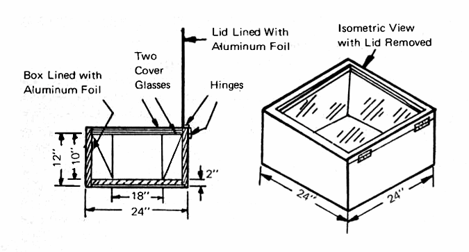
One of the best solar ovens, little known in this country, was developed by Dr. M. K. Ghosh of Jamshedpur. Shown in Fig. 19, the Ghosh heater consists of a simple wooden box, about 24 inches square and 12 inches deep. It is lined with 2 inches of insulation (glass wool would be very satisfactory here) and it contains a blackened metal liner in which the cooking is done. The interior insulation and the hinged top are lined with shiny aluminum foil, the former to reduce radiation from the oven to the sides and bottom of the box, and the latter to reflect the sun's rays into the oven through the double cover glasses. Since much of Inida lies near the equator and the sun is nearly overhead at midday, the Ghosh oven does an excellent job of cooking the noon meal.
FIG. 19 GHOSH-TYPE SOLAR OVEN (Top is hinged with two glass panes spaced 3/4" apart, sides and bottom of 3/8" plywood.)
Another type of oven, originated by Dr. Telkes, uses a metal box with double glazing over its open end and a hinged, insulated door at the other end. It is contained in a casing which may be made of metal or plywood, and the whole affair is arranged so that it can turn and tilt to follow the sun. Reflecting wings made of shiny aluminum (Alzak® is the best brand) are attached at an angle of 60 degrees to the plane of the cover glasses. These nearly double the amount of solar radiation which can enter the oven. On a bright sunny day, the Telkes ovens can get to 400°F from about 9:00 a.m. to 3:00 p.m.
A simplified version of the Telkes oven is described by Dan Halacy on pp. 51-62 of his excellent do-it-yourself handbook, Solar Science Projects (Appendix 4, No. 6). His oven uses the Telkes principle, but it sets the cover glasses at an angle of 45 degrees to the oven so that it does not need to be tilted.
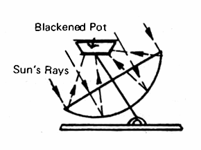
The basic principle of operation of a reflector-type solar cooker is shown in Fig. 20, where a simiple parabolic reflector, arranged on a sun-following mount, concentrates the sun's rays on a grill which can support a pot or a frying pan. This type of cooker will become hot just as soon as it is adjusted to face the sun and, according to Dr. Farrington Daniels, a 4 foot diameter reflector-type cooker will deliver the equivalent of a 400 watt electric hot plate under bright sunshine. He gives detailed instructions for the construction of a plastic shell of the proper shape which can be lined with aluminized Mylar. Appendix 4, No. 5, Chapter 5, pp. 89-103 covers the topic of solar cooking; pp. 102-103 gives an excellent bibliography on the subject.
FIG. 20 REFLECTOR COOKER (Must be adjustable to follow the sun)
FIG. 21 SOLAR CONCENTRATORS
Dan Halacy shows how to make an even simplier reflective cooker out of corrugated cardboard and kitchen-type aluminum foil on pp. 14-27 of Solar Science Projects (Appendix 4, No. 6). He advises the use of sun glasses when you are cooking with his aluminized broiler because the reflectance can be dazzling. The reflecting surface does not get hot, but the grill area does, so be careful when you put on the pots and pans. Also, Brace Research Institute, in How to Make a Solar Steam Cooker, Do-It-Yourself Leaflet L-2 ($1.00), describes a steam cooker which uses the simplest of materials for making a broiler. See Appendix 4, No. 2 for ordering information.
Solar Furnaces
While we are dealing with some of the higher temperature solar devices, mention should be made of solar furnaces which can produce small but extremely hot images of the sun. Fig. 21(a) shows the familiar magnifying glass which can be used to start a fire whenever the sun is shining. The diameter of available lenses is not great enough to do much real work with a burning glass. The Fresnel (pronounced Fra-nel') lens shown in Fig. 21(b) is available from Edmund Scientific Co. (Appendix 4, No. 12) in the form of a 12 inch square plastic sheet and you can also buy a booklet entitled Fun with Fresnel Lenses. Dan Halacy's book, Solar Science Projects, gives explicit details for making a mounting which will convert the Fresnel lens into a miniature solar furnace.
A concentrating curved-mirror solar furnace can reach extremely high temperatures (to 6,000°F, dpending on size). Control of the temperature of the target at the focal spot (Appendix 1) may be accomplished by using a diaphragm to "stop down" incoming rays, or by using a cylinder which can be moved to or fro along the axis of the concentrator to regulate the amount of radiation which reaches the target. Military surplus searchlights are the best source of high-precision reflectors at reasonable prices, and Edmund Scientific Co. frequently has some for sale.
The largest solar furnace now in existence is located at Odeillo in the French Pyrenees. There, starting in 1957, Dr. Felix Trombe and the National Center for Scientific Research have constructed a gigantic paraboloid which is nine stories high, uses 63 heliostats, each of which is 24 feet square, to produce an image which is a perfect circle, 12 inches in diameter. The furnace can concentrate 1,000 kilowatts of thermal energy into this small area and temperatures pushing up towards 6,000°F have been reached on sunny days. The first large American solar steam generator will probably be tested in this facility in the summer of 1975.
Electricity from the Sun
Photovoltaic Devices
About a century ago, when the scientific foundations were being laid for today's heliotechnology, a Frenchman, Becquerel, found that sunlight could produce minute amounts of electricity when it entered a very special kind of "wet cell" battery. Later on, other workers found that sunlight could change the resistance of certain metals and that very small amounts of electricity would be generated when sunlight illuminated discs of selenium or certain types of copper oxide. These devices were very useful as light meters but they could not produce enough power to do anything more strenuous than moving the pointer on a meter or activating a very sensitive relay.
In May, 1954 a one-page report, authored by D. M. Chapin, C. S. Fuller, and G. L. Pearson, appeared in the Journal of Applied Physics (Vol. 25, No. 5, p. 676). In brief terms they announced the discovery of a new treatment for ultra-pure silicon, which gave it the property of generating electricity from sunlight with a conversion efficiency of 6%. This was ten times better than any previous efficiency for the direct conversion of sunlight into electricity (the previous record was held by Dr. Telkes with a battery of thermocouples). Drs. Fuller, Chapin and Pearson immediately applied their invention to a small transistorized radio transmitter and receiver.
It was not until the U.S. embarked upon its space program late in 1957 that a unique application was found for the silicon solar battery. There was no other source of power for the satellites which we were planning to launch. NASA was persuaded to put silicon cells on its first permanent satellite, Vanguard One, which was orbited in 1958. They worked so well that all but one of the satellites which have been orbited since that that time have been powered by increasingly complex arrays of silicon cells and Skylab I produces some 20 kilowatts from its array of solar panels.
The details of the theory and construction of silicon cells are beyond the scope of this chapter, so it must suffice to say that, under bright sunlight, each 2 centimeter square cell will produce a short circuit current of 0.10 amperes (100 milliamperes) and an open circuit voltage of 0.60 (600 millivolts). Under optimum load, they produce about 90 milliamps at 400 millivolts, or approximately 36 milliwatts. This is certainly a tiny amount of power when it is compared with today's gigantic steam turbo-generators; but silicon cell technology has advanced so rapidly that tends of thousands of individual cells can be connected together. This can be done rapidly and reliably so that today the communications satellite has become the standard means of intercontinental communication for voice, television and even computer language.
Although the cost is still to high for the installation of great panels of solar cells on every rooftop, great strides have been made and the cost has been reduced from $1000 per watt to $20 per watt, with more reductions on the way. Ways of producing far less expensive silicon cells are now under intensive study. Another approach is to concentrate ten times as much sunshine onto the cells as they would normally receive. The main problem here is to remove the heat which will build up if the cells are not cooled effectively. The more optimistic silicon cell specialsts think that, within another decade, the costs will come down to $2 per watt, which will be competitive with conventional methods of power generation.
Although making silicon cells is not a do-it-yourself project, from time to time bargains are available in the way of space-reject cells (Herbach and Rademan of Philadelphia (Appendix 4, No. 13) is an excellent source), and these are well worth considering for powering radios and other apparatus which require very small amounts of power. Fig. 22 shows a method of mounting solar cells on a sun-tracking device to obtain more power than can be gained from a fixed array. The circuit diagram indicates a series-connected battery of cells which can produce any desired voltage (just use twice as many cells as you need volts, since under load each cells will give just about 1/2 volt). A number of such series-connected groups connected in parallel can produce a respectable amount of power and keep a 12-volt storage battery charged for running a radio or even a small TV set. We are not yet at the point where solar cells will run air conditioners or other large motor loads, but Dr. Böer believes that he can produce another type of cell, using cadmium sulfide rather than silicon, which can be produced at far lower cost than the silicon cells and still retain adequate efficiency to do the job.
FIG. 22 SOLAR ELECTRIC GENERATOR USING SILICON CELLS
Heliothermal Generators
There have been many attempts to produce steam from heliothermal devices, beginning with John Ericsson's work in New York just after the Civil War and reaching its high point early in the 1900's with the building of great solar engines in Arizona and California by A. G. Eneas and in Egypt by F. Shuman and C. V. Boys. None of these attempts succeeded for reasons which are too numerous to be mentioned here.
Flat plate collectors cannot attain temperatures much above 200°F and engines operating at temperatures in that range and discharging their waste heat to air at 80 to 90°F offer little prospect of generating useful amounts of power. Concentrating collectors which do not yet exist, except for laboratory prototypes, are needed to reach temperatures high enough to make engines or turbines operate with competitive efficiencies. When these become available, they will probably use vapors of the Freon family rather than water and they will use the cycle pioneered a century ago by an Englishman, Rankine. For a more detailed account of the various heat engine cycles, read Chapter 7, Introduction to the Utilization of Solar Energy (Appendix 4, No. 3).
Today's research efforts in the field of heliothermal power generation fall into two categories: (A) small engines using Freon vapor to produce 5 to 10 horsepower to drive pumps, generators or refrigeration compressors and (B) very large installations using vast areas of concentrating collectors to produce enough steam to run a boiler mounted on a tower of moderate height. This is surrounded by a great field of slightly curved mirrors which turn and tilt to reflect the sun's rays into the boiler and thus to produce steam.
The storage of heat to run the solar-power engine at night or on partially cloudy days is a problem which is not even close to solution, so present thinking is that solar steam stations will be tied in with the existing electric power grids. Solar plants will contribute power to the grid when the sun is shining, thus conserving fuel which would otherwise have been burned or water which would have to turn through turbines. The solar plants would be idle at night, when the demand for power in today's air conditioned world is low.
Sundials and the Telling of Time
The use of shadows cast by the sun on the earth to designate the passage of time is so ancient that no one really knows who built the first sun dial. They were certainly in use by 1500 B.C. (see Appendix 4, No. 14 for a comprehensive study of the science of "dialing") and a bewildering variety of sundials is to be found in Europe and Asia. The Simplest and most widely used type is the horizontal dial.
The dial plate is the base upon which the hour lines are inscribed and the "gnomon," attached to the plate and pointing true north (not compass north!), is the element which casts the shadow. The angle between the gnomon and the base must be exactly equal to the local latitude and then, for reasons which an astronomer can readily explain, the gnomon will be aligned exactly with the earth's axis. The hour lines for a properly constructed horizontal dial will always denote the number of hours away from solar noon, and so corrections must be made to account for the Equation of Time and departure of the local longitude from the Local Standard Time Meridian. These corrections are explained in Appendix 2, and the details for calculating hour line angles are given in Appendix 4, No. 14.
Conclusions
The purpose of this chapter has been to give the reader the basic principles upon which the rapidly growing field of heliotechnology is based. For those who want to learn more about this fascinating field, the list of sources given in Appendix 4 will prove to be exceedingly helpful. Regular reading of Solar Energy, the Journal of the International Solar Energy Society, will help, too.